PCB fabrication
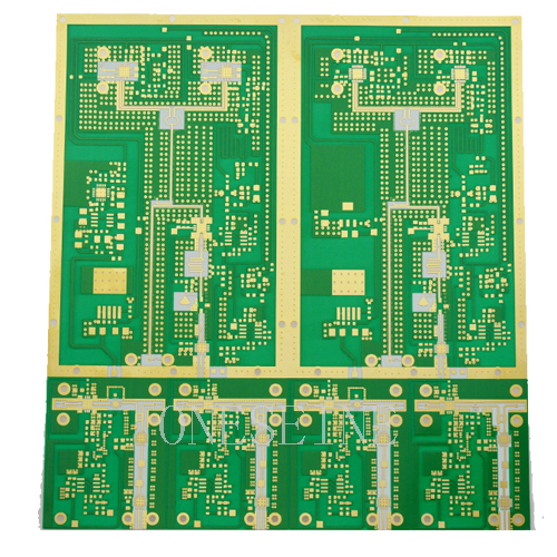
Double Sided Rogers 4003C Automotive Radar PCB Circuit Board With Low z-axis CTE
Double Sided Rogers 4003C Automotive Radar PCB Circuit Board With Low z-axis CTE
Application: Automotive System
PCB material:Rogers 4003C 12mil
Surface finish:Immersion gold
Name: Automotive System Double Sided Rogers 4003C High Frequency Material PCB Circuit Board
Board size:9*13CM
Solder mask:Green
Typical Applications:
Automotive radar applications
Global positioning satellite antennas
Cellular telecommunications systems - power amplifiers and antennas
Patch antenna for wireless communications
Direct broadcast satellites
RFID Tags
Surface mount RF components
E-Band point to point microwave links
1. Rogers pcb multilayer pcb with high frequency can improvide the products quality ,with high techolonogy treatment improve the life cycle of the products .
2. Immersion gold surface finish make the pcb 's conductive performance enhancements.
3. Multilayer pcb design ,the precision of the pcb improves much more better .
4. Low dielectric : 3 dielectric conductivity much more precision .
Double-Sided Rogers 4003C Automotive Radar PCB Circuit Board With Low Z-axis CTE
Overview and Core Advantages
This double-sided Printed Circuit Board (PCB) is fabricated on Rogers RO4003C high-frequency laminate, representing an optimal engineering solution for the demanding performance, reliability, and cost requirements of modern automotive radar systems. It is particularly suited for high-volume applications such as 24 GHz Short-Range Radar (SRR) found in Advanced Driver-Assistance Systems (ADAS). The defining feature of this board is its low Z-axis Coefficient of Thermal Expansion (CTE), a critical property that ensures exceptional dimensional stability. Throughout the severe temperature cycles experienced in automotive environments—from freezing cold starts to high under-hood operational heat—the board's thickness remains stable. This directly prevents stress and potential failure in the plated through-holes (vias), guaranteeing long-term interconnect reliability and consistent electrical performance over the entire lifespan of the vehicle.
Material Properties and Performance Characteristics
The Rogers RO4003C material is a glass-reinforced hydrocarbon and ceramic composite engineered for performance-sensitive commercial RF applications. It provides a stable dielectric constant (Dk) of 3.55 ± 0.05 at 10 GHz, which is crucial for predictable signal propagation speed and accurate radar phase calculations. The material exhibits a low dissipation factor (Df) of 0.0027, minimizing signal loss to help maximize radar detection range and sensitivity. It is designed for thermal robustness with a high glass transition temperature (Tg) and a reliable operating range from -55°C to +150°C, easily withstanding solder reflow processes and harsh under-hood conditions. Furthermore, its low moisture absorption rate maintains stable electrical properties in humid environments, and it carries a UL 94 V-0 flame rating, meeting stringent automotive safety standards.
Design for Manufacturing and Reliability
A significant advantage of the RO4003C material is its excellent compatibility with standard FR-4 epoxy/glass PCB manufacturing processes. Unlike pure PTFE-based RF materials, it does not require specialized drilling or plating chemistries, which significantly reduces processing costs, simplifies the supply chain, and enables faster production lead times—key factors for automotive electronics. This double-sided configuration offers excellent design flexibility for integrating antenna patches, transmission lines, and control circuitry on a compact board. For optimal high-frequency performance, designs should utilize smooth, low-profile copper foil to minimize conductor loss. The combination of its inherent thermal properties and manufacturing compatibility makes this PCB an ideal candidate for automotive-grade reliability testing. Partnering with manufacturers certified to the IATF 16949 quality management standard is recommended to ensure full compliance with automotive industry requirements.
Typical Applications and Key Specifications
This PCB is specifically engineered for ADAS functions enabled by short-range radar. Primary applications include the core sensor boards for 24 GHz radar used in Blind-Spot Detection (BSD), Lane Change Assist (LCA), and Rear Cross-Traffic Alert (RCTA) systems. It serves as an excellent platform for the RF front-end and antenna arrays within these radar modules. Key specifications for design reference include the use of Rogers RO4003C as the base laminate in a standard two-layer construction. Common dielectric thicknesses range from 0.254mm (10 mil) to 0.762mm (30 mil), clad with either 0.5 oz or 1 oz copper foil. Surface finishes such as Immersion Silver (ImAg) or Electroless Nickel Immersion Gold (ENIG) are recommended for superior solderability and high-frequency performance. Maintaining tight impedance control (typically 50Ω ±5%) and precise trace geometry is standard practice to ensure optimal signal integrity for radar operation
Categories
News
Contact Us
Contact: Flexible PCB
Phone: 0086 18682010757
E-mail: kico@oneseine.com
Add: BldB,Fushan Industrial Park,Qianwu Town,Doumen,Zhuhai,China
