PCB fabrication
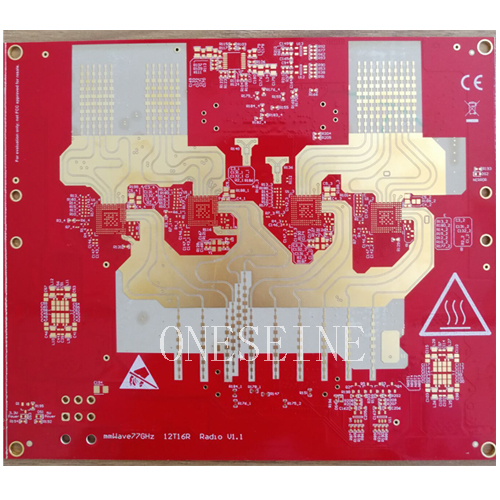
77GHz mmWave Anticollision Radar PCB | 10-Layer Mixed-Dielectric Rogers RO3003G2 + RO4835LoPro + Isola 370HR Stack-Up
77GHz mmWave Anticollision Radar PCB | 10-Layer Mixed-Dielectric Rogers RO3003G2 + RO4835LoPro + Isola 370HR Stack-Up
This article presents a high-performance 77GHz millimeter-wave (mmWave) anticollision radar PCB circuit board designed for automotive ADAS (Advanced Driver Assistance Systems) and autonomous driving applications. The board features a 10-layer mixed-dielectric stack-up combining Rogers RO3003G2, Rogers RO4835LoPro, and Isola 370HR materials — an architecture that delivers the ultra-low RF loss required for 77GHz antenna and radar front-end circuits while maintaining cost efficiency for digital and power sections. Manufactured with ENIG (Electroless Nickel Immersion Gold) surface finish and precise impedance control, this PCB is engineered for the demanding performance and reliability requirements of automotive millimeter-wave radar.
ONESEINE TECHNOLOGY CO.LTD has extensive experience manufacturing mixed-dielectric, high-frequency PCBs for 77GHz automotive radar, 5G communication, and aerospace applications — combining advanced lamination, drilling, and plating capabilities to deliver boards that meet the strict tolerances of mmWave circuits.
1. Product Specifications Overview
The 77GHz anticollision radar PCB is defined by the following key specifications:
Product name: 77GHz Millimeter-Wave Anticollision Radar PCB Circuit Board
Material: Mixed stack-up of Rogers RO3003G2 + Rogers RO4835LoPro + Isola 370HR
Layer count: 10 layers
Board size: 180mm × 220mm
Board thickness: 2.8mm
Surface finish: ENIG (Electroless Nickel Immersion Gold)
Application: Automotive anticollision radar (77GHz mmWave)
These specifications reflect a board optimized for the unique challenges of 77GHz mmWave radar — where signal loss, impedance consistency, thermal stability, and manufacturing precision are critical to radar detection range, resolution, and reliability.
2. 77GHz mmWave Radar: The Core Sensor for Automotive Safety
The 77GHz frequency band (76–81GHz) has become the global standard for automotive radar, replacing the older 24GHz band for new vehicle designs. The shift to 77GHz is driven by several key advantages:
Wider bandwidth: The 77GHz band supports up to 4GHz of continuous bandwidth (76–81GHz), compared to only ~250MHz for the 24GHz band. This wider bandwidth enables dramatically better range resolution — as fine as 4cm at 77GHz, versus ~75cm at 24GHz — allowing the radar to distinguish between closely spaced objects such as a pedestrian and a nearby vehicle.
Smaller antenna size: At 77GHz, the wavelength is approximately 3.9mm, allowing antenna arrays to be much more compact than at 24GHz. This enables smaller, more aerodynamically integrated radar modules that can be discreetly mounted behind vehicle bumpers, grilles, or side panels.
Higher angular resolution: The combination of higher frequency and compact multi-element antenna arrays (often 12TX × 16RX or more for imaging radar) enables precise angle-of-arrival measurement, supporting 3D point-cloud radar that can classify objects by shape and position.
Global regulatory alignment: The 76–81GHz band is allocated for automotive radar in most major markets (Europe, US, China, Japan), enabling global platform designs.
77GHz radar is a critical sensor for a wide range of ADAS functions, including:
ACC (Adaptive Cruise Control): Maintains safe following distance by detecting vehicle speed and distance ahead.
AEB (Autonomous Emergency Braking): Detects imminent collisions and applies brakes automatically.
BSD (Blind Spot Detection): Monitors adjacent lanes for vehicles in the driver's blind spot.
LCA (Lane Change Assist): Helps drivers make safe lane changes by detecting approaching vehicles.
RCTA (Rear Cross-Traffic Alert): Warns of crossing traffic when reversing out of parking spaces.
Automated parking: Uses short-range radar to detect obstacles and guide parking maneuvers.
Autonomous driving: Serves as a key sensor alongside cameras and LiDAR for L2+ to L4 autonomous driving systems.
The PCB is the foundation of the radar module, hosting the antenna array, RF front-end MMIC (Monolithic Microwave Integrated Circuit), signal processing components, power management, and digital control circuits. Its performance directly determines the radar's detection range, accuracy, and immunity to interference.
3. Mixed-Dielectric Stack-Up: Why Three Materials?
The 10-layer board uses a mixed-dielectric stack-up combining three different materials — Rogers RO3003G2, Rogers RO4835LoPro, and Isola 370HR — each selected for a specific function in the radar system. This hybrid approach is a common and cost-effective strategy for mmWave radar PCBs, where pure high-frequency laminate would be prohibitively expensive for the entire board, but standard FR-4 cannot meet the RF performance requirements.
3.1 Rogers RO3003G2: Ultra-Low-Loss mmWave Substrate
Rogers RO3003G2 is a ceramic-filled PTFE (polytetrafluoroethylene) composite laminate engineered specifically for millimeter-wave and high-frequency applications. Its key properties include:
Dielectric constant (Dk): 3.00 ± 0.04 @ 10GHz — tightly controlled for consistent impedance and antenna performance.
Dissipation factor (Df): 0.0010 @ 10GHz — extremely low, minimizing dielectric loss at 77GHz where even small losses significantly reduce radar range.
Low moisture absorption: Ensures stable electrical performance in humid automotive environments.
Excellent dimensional stability: Maintains tight registration tolerances for fine-line mmWave circuits.
In the radar PCB, RO3003G2 is typically used for the antenna layer and critical RF transmission lines — where signal loss directly impacts radar sensitivity and detection range. The ultra-low Df ensures that the 77GHz signal radiated from or received by the antenna suffers minimal attenuation before reaching the RF front-end.
3.2 Rogers RO4835LoPro: High-Performance RF Substrate with Low-Profile Copper
Rogers RO4835LoPro is a ceramic-filled, thermoset hydrocarbon laminate that bridges the gap between PTFE high-frequency materials and standard FR-4. Its key properties include:
Dielectric constant (Dk): 3.48 ± 0.05 @ 10GHz.
Dissipation factor (Df): 0.0037 @ 10GHz — low enough for many RF applications while offering better mechanical rigidity and lower cost than PTFE.
LoPro (Low-Profile) reverse-treated copper foil: The LoPro copper has a very smooth surface, which significantly reduces conductor loss (skin effect loss) at high frequencies — a critical advantage at 77GHz where conductor roughness can dominate total transmission line loss.
Good thermal conductivity: Aids heat dissipation from RF power amplifiers and processing chips.
RO4835LoPro is typically used for RF front-end transmission lines, power amplifier sections, and intermediate-frequency (IF) circuits — where low loss is important but the ultra-low Df of RO3003G2 is not strictly necessary, allowing cost optimization.
3.3 Isola 370HR: High-Tg FR-4 for Digital and Power Sections
Isola 370HR is a high-Tg (glass transition temperature) FR-4 epoxy glass fabric laminate designed for high-layer-count, high-reliability applications. Its key properties include:
Tg (glass transition temperature): ~170°C (by DSC) — significantly higher than standard FR-4 (~130–140°C), providing improved thermal stability for lead-free assembly and automotive under-hood / behind-bumper environments.
Good CAF (Conductive Anodic Filament) resistance: Reduces the risk of electrochemical migration between closely spaced vias and conductors in high-humidity environments.
Cost efficiency: A fraction of the cost of Rogers high-frequency laminates.
370HR is used for the digital signal processing layers, power distribution layers, and control circuits — where high-frequency performance is not required, but thermal reliability, signal integrity for high-speed digital signals, and cost efficiency are priorities.
3.4 Advantages of the Mixed-Dielectric Approach
By combining these three materials in a single 10-layer stack-up, the radar PCB achieves:
Optimal RF performance where it matters most (antenna and critical RF paths using RO3003G2).
Balanced cost and performance for secondary RF paths (RO4835LoPro).
Cost efficiency and thermal reliability for digital and power sections (Isola 370HR).
Integrated solution: All circuitry — antenna, RF, analog, digital, and power — on a single board, reducing inter-board connections and improving reliability.
However, mixed-dielectric lamination is technically challenging. Different materials have different coefficients of thermal expansion (CTE), resin flow characteristics, and drilling behaviors — requiring precise process control to ensure reliable lamination without delamination, voids, or registration errors. ONESEINE TECHNOLOGY CO.LTD has developed specialized mixed-dielectric lamination processes, including optimized press profiles (temperature ramp, pressure stages, and cure time), compatible prepreg selection, and controlled drilling parameters — enabling reliable production of Rogers + FR-4 hybrid boards for 77GHz radar and other high-frequency applications.
4. 10-Layer Stack-Up Architecture
A typical 10-layer stack-up for a 77GHz radar PCB is structured to optimize signal integrity, RF performance, power distribution, and thermal management. While the exact layer assignment depends on the specific design, a common architecture includes:
Top layer (Layer 1): Antenna array and RF components — typically using Rogers RO3003G2 for the antenna substrate. The antenna is often a series-fed patch array or a corporate-fed array, with element spacing optimized for 77GHz (approximately λ/2 ≈ 1.95mm at 77GHz).
Layer 2: Ground plane — provides a continuous reference for the antenna and RF transmission lines, critical for controlled impedance and radiation pattern control.
Layer 3: RF transmission lines and RF front-end circuitry — using RO4835LoPro for low-loss interconnects between the antenna, MMIC, and IF stages.
Layer 4: Ground / power plane — isolates RF sections from digital sections and provides low-inductance return paths.
Layer 5–6: High-speed digital signal layers — using Isola 370HR for signal processing, data interfaces (e.g., CAN, Ethernet, LVDS), and control signals. These layers require controlled impedance (typically 50Ω single-ended, 90Ω or 100Ω differential).
Layer 7: Power plane — distributes regulated supply voltages to digital and analog components.
Layer 8: Ground plane — provides a solid reference for the bottom-side components and shields against EMI.
Layer 9: Secondary signal / power layer — for additional routing and power distribution.
Bottom layer (Layer 10): Component side — hosting connectors, power management ICs, and secondary components.
This layer count and structure provide sufficient routing density for a modern 77GHz radar module while maintaining the signal isolation and impedance control required for mmWave performance. The total board thickness of 2.8mm is consistent with a 10-layer mixed-dielectric construction, with dielectric thicknesses carefully selected to achieve target impedances (50Ω for RF lines, controlled differential impedances for high-speed digital) and mechanical rigidity.
5. ENIG Surface Finish: Why It Matters for mmWave Radar
The board uses ENIG (Electroless Nickel Immersion Gold) surface finish — a common and well-suited choice for high-frequency and automotive PCBs. ENIG deposits a layer of electroless nickel (typically 3–6μm) followed by a thin immersion gold layer (0.05–0.15μm) over exposed copper pads and traces.
The advantages of ENIG for 77GHz radar PCB include:
Excellent solderability: The gold surface prevents oxidation, ensuring reliable soldering of fine-pitch RF components and BGA packages — critical for automotive quality standards.
Flat, coplanar surface: ENIG provides a very flat pad surface, which is important for fine-pitch components and for maintaining consistent gap heights in flip-chip or MMIC assembly.
Good high-frequency performance: The thin gold layer has minimal impact on RF signal loss at 77GHz, and the nickel layer provides a good barrier against copper diffusion.
Corrosion resistance: The gold layer protects against oxidation and corrosion in the harsh automotive environment (temperature cycling, humidity, road salt).
Compatibility with multiple assembly processes: ENIG supports lead-free reflow, wire bonding (with appropriate nickel/gold thickness), and press-fit connectors.
For mmWave antenna pads and RF transmission lines, the surface finish must be carefully controlled — excessive nickel thickness or gold roughness can introduce additional conductor loss at 77GHz. ONESEINE TECHNOLOGY CO.LTD maintains tight process control over ENIG plating parameters to ensure consistent, low-loss surface finishes for high-frequency boards.
6. Manufacturing Challenges for 77GHz Radar PCB
Producing a 10-layer mixed-dielectric 77GHz radar PCB requires overcoming several significant manufacturing challenges:
Mixed-dielectric lamination: Bonding PTFE-based Rogers materials (which have low surface energy and are inherently difficult to bond) with FR-4 requires specialized surface treatment (e.g., plasma etching or chemical roughening), compatible prepreg systems, and optimized press profiles. The different CTE values of the materials can cause stress, warpage, or delamination if not properly managed.
Precision drilling: Drilling through mixed materials — including abrasive ceramic-filled PTFE and glass-reinforced FR-4 — requires optimized drill parameters (speed, feed rate, drill bit geometry, and peck cycles) to prevent smear, nail-heading, or rough hole walls that could compromise plating quality. Via holes must be clean and smooth for reliable copper plating, especially for via-in-pad designs common in RF circuits.
Fine-line imaging: 77GHz RF transmission lines and antenna elements require fine line widths and tight tolerances. At 77GHz, even small variations in line width or dielectric thickness can cause impedance mismatches and signal loss. High-precision LDI (Laser Direct Imaging) with registration accuracy of ±10μm or better is required.
Impedance control: RF lines must maintain 50Ω characteristic impedance with tight tolerances (typically ±5% or better). This requires precise control of dielectric thickness, line width, copper thickness, and reference plane continuity across the mixed-dielectric stack-up.
Plating and surface finish: Through-hole plating, via filling, and ENIG surface finish must be uniform and defect-free — especially for RF ground vias that provide critical shielding and grounding for mmWave circuits.
Thermal management: 77GHz radar MMICs and power amplifiers generate significant heat. The PCB must provide effective thermal paths — including thermal vias, copper pours, and thermally conductive dielectrics — to keep components within their operating temperature range in the automotive environment (−40°C to +85°C or higher).
Automotive reliability: The board must pass stringent automotive qualification tests, including thermal cycling (−40°C to +125°C), humidity testing (85°C/85% RH), vibration, and mechanical shock — requiring robust material selection, lamination quality, and plating integrity.
ONESEINE TECHNOLOGY CO.LTD addresses these challenges through its advanced manufacturing capabilities: high-precision LDI imaging, controlled-impedance processing, mixed-dielectric lamination expertise, laser drilling (minimum 3mil), mechanical drilling (minimum 0.10mm), and comprehensive quality inspection including AOI (Automated Optical Inspection), impedance testing, and microsection analysis. The company's experience with high-frequency boards, 32-layer constructions, and mixed-dielectric stack-ups makes it a capable partner for 77GHz automotive radar PCB production.
7. ONESEINE TECHNOLOGY CO.LTD: High-Frequency PCB Manufacturing Capabilities
ONESEINE TECHNOLOGY CO.LTD is a PCB manufacturer with specialized expertise in high-frequency, high-layer-count, and mixed-dielectric circuit boards — including 77GHz automotive radar PCBs, 5G communication boards, and aerospace RF assemblies. The company's relevant capabilities include:
Mixed-dielectric / mixed-pressure boards: Experienced in laminating Rogers (RO4000 series, RO3000 series, RT/duroid), Panasonic Megtron, Isola, and ShengYi high-frequency materials with FR-4 and high-Tg substrates in a single stack-up.
High-layer-count production: Up to 32-layer board technology, supporting complex radar, communication, and server designs.
High-precision manufacturing: Minimum line width/spacing of 2.0/2.0mil (50/50μm), minimum mechanical drilling of 0.10mm, minimum laser drilling of 3mil, and board thickness-to-hole-diameter aspect ratio up to 26:1.
Impedance control: High-precision single-ended and differential impedance control for RF (50Ω), high-speed digital, and differential signaling standards.
Surface finishes: ENIG, HASL lead-free, OSP, immersion silver, and other finishes — with tight process control for high-frequency applications.
Thick-copper capability: Up to 15oz copper for power electronics and thermal management.
Rigid-flex and HDI: Supporting compact, high-density radar module designs.
Quality certifications: Shenzhen High-Tech Enterprise and National High-Tech Enterprise, with a commitment to stable quality and fast delivery for both prototyping and mass production.
With these capabilities, ONESEINE TECHNOLOGY CO.LTD is well-positioned to manufacture the 77GHz anticollision radar PCB described in this article — and to support automotive Tier-1 suppliers and radar module designers with reliable, high-performance mmWave PCB solutions.
8. Conclusion
The 77GHz mmWave anticollision radar PCB represents the intersection of advanced materials science, precision manufacturing, and automotive safety technology. Its 10-layer mixed-dielectric stack-up — combining Rogers RO3003G2 for ultra-low-loss antenna and RF circuits, Rogers RO4835LoPro for high-performance RF interconnects, and Isola 370HR for reliable digital and power sections — delivers the performance required for 77GHz radar while maintaining cost efficiency. The ENIG surface finish, precise impedance control, and robust construction ensure reliable operation in the demanding automotive environment.
As automotive safety regulations tighten and autonomous driving technology advances, demand for 77GHz radar PCBs will continue to grow — requiring PCB manufacturers with specialized expertise in high-frequency materials, mixed-dielectric lamination, and precision manufacturing. ONESEINE TECHNOLOGY CO.LTD, with its proven capabilities in high-frequency, high-layer-count, and mixed-dielectric PCB production, is well-equipped to meet this demand and support the next generation of automotive safety systems.
SEO Keywords
77GHz mmWave radar PCB, automotive anticollision radar circuit board, Rogers RO3003G2 PCB, Rogers RO4835LoPro, Isola 370HR mixed stack up, 10 layer mixed dielectric PCB, ENIG surface finish high frequency, ADAS radar PCB, 77GHz antenna PCB, mmWave radar PCB manufacturer, automotive radar PCB China, ONESEINE TECHNOLOGY high frequency PCB, Rogers FR4 hybrid PCB, 76-81GHz radar board, controlled impedance RF PCB, mixed pressure lamination PCB, 5G mmWave PCB, PTFE PCB manufacturing, automotive grade PCB, radar front end PCB
Categories
News
Contact Us
Contact: Flexible PCB
Phone: 0086 18682010757
E-mail: kico@oneseine.com
Add: BldB,Fushan Industrial Park,Qianwu Town,Doumen,Zhuhai,China









